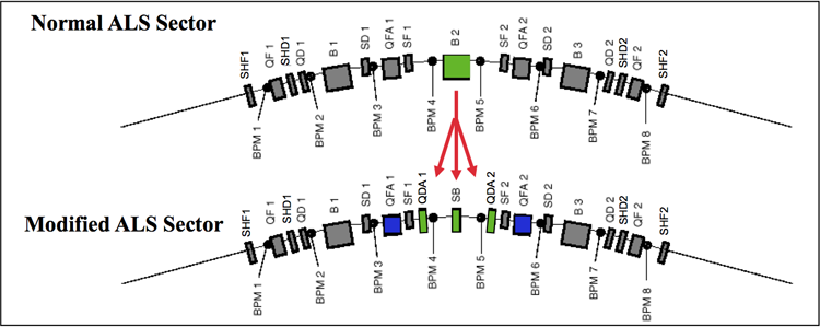
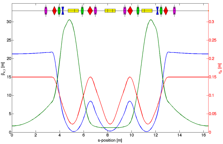
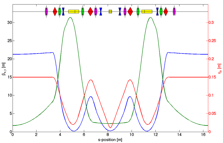
STORAGE-RING PARAMETERS: General technical information, horizontal and vertical lattice functions, and arc lattice functions (normal and superbends).
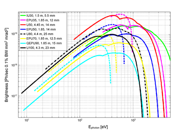
PHOTON-SOURCE PARAMETERS: Brightness curves for bend magnets, superbends, and insertion devices. Insertion-device information includes energy ranges, number of periods, period length and operating-gap ranges for ALS undulators and wigglers.
General Parameters
| Parameter | Value |
| Beam particle | electron |
| Beam energy | 1.9 GeV |
| Injection energy | 1.9 GeV |
| Beam current (all operation is in top-off with ΔI/I ≤ 0.3%) | 500 mA in multibunch mode |
| Filling pattern | 256–320 bunches; possibility of one 5- to 6-mA “camshaft” bunch in the filling gap |
| Bunch spacing: multibunch mode | 2 ns |
| Circumference | 196.8 m |
| Number of straight sections | 12 |
| Number of insertion devices | 12 |
| Radio frequency | 499.642 MHz (±6 kHz) |
| Beam size in straight sections, rms (1.9 GeV multibunch mode) | 251 µm x 8 µm (horizontal x vertical) |
| Top-off injection rate | 0.5–1.0 mA/shot every 13–40 seconds |
| Horizontal emittance | 2.0 nm·rad |
| Vertical emittance | 0.04 nm·rad |
| Energy spread (ΔE/E, rms) | 0.95 x 10⁻³ |
| Pulse Length (FWHM) | 60 ps* |
| *The bunch length is deliberately increased using harmonic cavities to improve the beam lifetime. | |

Horizontal and Vertical Lattice Functions (α, β, γ), Horizontal Dispersion Functions (ηx and ηx′),
and 1-σ Beam Sizes (σ) and Divergences (σ′) at Photon Source Points*
| BEAM PORT |
ANGLE** [DEGREES] | DEVICE | AXIS | α |
β [m] |
γ [m-1] |
ηx [m] |
ηx′ | σ [µm] | σ′ [µrad] |
| BL x.0 | 0.0 | Insertion device | x | 0.000 | 21.27 | 0.047 | 0.15 | 0.000 | 251 | 9.7 |
| BL x.0 | 0.0 | Insertion device | y | 0.000 | 1.72 | 0.581 | 8.3 | 4.8 | ||
| BL x.0.1 | 0.0 | Upstream insertion device | x | 0.061 | 21.34 | 0.047 | 0.15 | 0.000 | 251 | 9.7 |
| BL x.0.1 | 0.0 | Upstream insertion device | y | 0.756 | 2.7 | 0.581 | 10.4 | 4.8 | ||
| BL x.0.2 | 0.0 | Downstream insertion device | x | -0.06 | 21.35 | 0.047 | 0.15 | 0.000 | 251 | 9.7 |
| BL x.0.2 | 0.0 | Downstream insertion device | y | -0.76 | 2.7 | 0.581 | 10.4 | 4.8 | ||
| BL x.1 | 6.3 | Bending magnet | x | -0.34 | 0.23 | 0.047 | 0.026 | 0.043 | 32.7 | 106.4 |
| BL x.1 | 6.3 | Bending magnet | y | 9.177 | 26.55 | 3.209 | 32.6 | 11.3 | ||
| BL x.2 | 12.6 | Bending magnet | x | 0.685 | 0.48 | 3.085 | 0.027 | -0.05 | 40.3 | 89.7 |
| BL x.2 | 12.6 | Bending magnet | y | -0.05 | 1.28 | 0.786 | 7.1 | 5.6 | ||
| SB BL x.2 | 12.6 | Superbend magnet | x | 0.226 | 0.28 | 3.811 | 0.012 | -0.04 | 26.2 | 95.8 |
| SB BL x.2 | 12.6 | Superbend magnet | y | 0.027 | 2.28 | 0.439 | 9.5 | 4.2 | ||
| BL x.3 | 17.4 | Bending magnet | x | -0.69 | 0.48 | 3.085 | 0.027 | 0.046 | 40.3 | 89.7 |
| BL x.3 | 17.4 | Bending magnet | y | 0.045 | 1.28 | 0.786 | 7.1 | 5.6 | ||
| SB BL x.3 | 17.4 | Superbend magnet | x | -0.23 | 0.28 | 3.811 | 0.012 | 0.042 | 26.2 | 95.8 |
| SB BL x.3 | 17.4 | Superbend magnet | y | -0.03 | 2.28 | 0.439 | 9.5 | 4.2 | ||
| BL x.4 | 22.6 | Bending Magnet | x | 0.827 | 0.34 | 4.923 | 0.031 | -0.06 | 39.4 | 116.2 |
| BL x.4 | 22.6 | Bending Magnet | y | -10.7 | 24.26 | 4.685 | 31.4 | 13.7 | ||
 *These are generic lattice functions. There are small sector-to-sector variations in the parameters for a given source angle because of the distortion in the lattice functions of the superbends and the insertion devices. For more precise information, contact Christoph Steier. *These are generic lattice functions. There are small sector-to-sector variations in the parameters for a given source angle because of the distortion in the lattice functions of the superbends and the insertion devices. For more precise information, contact Christoph Steier.**Angle refers to the direction of the radiation from the source point, as shown at right. |
||||||||||
Normal-Arc Lattice-Function Plot
Superbend-Arc Lattice Function Plot
Summary Graph of Brightness Curves for All Insertion Devices
Insertion-Device and Bend-Magnet Parameters
The ALS has six elliptically polarizing undulators, two in straight 4, two in straight 11, and one each in straights 6 and 7. All are arranged with chicanes so that two such devices can be installed to feed two independent beamlines. They can be used in a variety of polarization modes, including circular, elliptical, horizontal, and vertical. These modes can be chosen by appropriate phasing of the magnet rows. The brightness and flux curves below are shown for horizontal and circular polarization. Curves for elliptical and vertical polarization are similar to the horizontal polarization curve, but the minimum photon energy is higher.
- Elliptical Polarization Undulator (EPU35)
- Elliptical Polarization Undulator (EPU50)
- Elliptical Polarization Undulator (EPU70)
- Quasiperiodic Elliptical Polarization Undulator (QEPU90)
Note: Brightness and flux were calculated at a machine energy of 1.9 GeV, 500 mA current, vertical emittance of 40 x 10-12m·rad, horizontal emittance of 2.0 x 10⁻⁹ m·rad, and lattice parameters as listed in the Storage Ring Parameters.
Insertion-Device Parameters
| DEVICE | BEAMLINE | ENERGY RANGE (AT 1.9 GeV) |
PERIOD LENGTH |
NO. OF PERIODS |
OPERATING GAP RANGE |
EFFECTIVE FIELD RANGE |
| U30 Undulator | 6.0.1 | 120–5000 eV 4000–11000 eVd |
30 mm | 50 | 5.5–2.7 mm | 1.5–0.13 T |
| U50 Undulator | 8.0.1 | 80–3000 eV | 50 mm | 89 | 14–45 mm | 0.85–0.10 T |
| U80 Undulator | 12.0.1 | 20–1900 eV | 80 mm | 55 | 24.7–83 mm | 0.80–0.07 T |
| U100 Undulator | 9.0.1 | 8–1500 eV | 100 mm | 43 | 22.7–116 mm | 0.98–0.05 T |
| U100 Undulator | 10.0.1 | 12–1500 eV | 100 mm | 43 | 23.1–116 mm | 0.80–0.05 T |
| EPU35 Elliptical Polarization Undulator | 6.0.2 |
265–4000 eVa |
35 mm | 52.5 | 12–40 mm | 0.71–0.06 T |
| EPU50 Elliptical Polarization Undulator | 4.0.2 | 73–3000 eVa | 50 mm | 37 | 14–55 mm | 0.80–0.10 Tb 0.58–0.10 Tc |
| EPU50 Elliptical Polarization Undulator | 11.0.1 | 75–3000 eVa | 50 mm | 36.5 | 14.3–55 mm | 0.85–0.10 Tb 0.57–0.10 Tc |
| EPU50 Elliptical Polarization Undulator | 11.0.2 | 71–3000 eVa | 50 mm | 37 | 13.8–55 mm | 0.86–0.10 Tb 0.58–0.01 Tc |
| EPU70 Elliptical Polarization Undulator | 7.0.2 | 16–2000 eVa | 70 mm | 26.5 | 12.5–75 mm | 1.18–0.07 T |
| W114 Wiggler | 5.0.1 5.0.2 5.0.3 |
6–21,000 eVd | 114 mm | 29 | 12.5–180 mm | 1.94–0.03 T |
| QEPU90 | 4.0.3 | 8–1600 eVa | 90 mm | 20.5 | 14.5–99 mm | 1.18–0.06 Tb 0.78–0.06 Tc |
| a Elliptical polarization mode. b Vertical field. c Horizontal field. d Wiggler mode. | ||||||